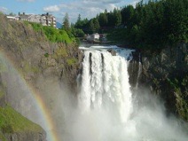
The Snoqualmie Falls in the state of Washington are truly beautiful. Higher than Niagara Falls, they provide an ideal location for a hydro power plant. Charles Baker was a civil engineer working for the railroads, with an expertise in tunneling and blasting. He saw the waterfall when he was working for the railroad and recognized its potential. His work with the railroad complete, he was unemployed when he approached his wealthy father about financing the power project. His father approved, and the power plant was built and went into service on July 31, 1899.
Two things are significant about this power plant. It was one of the first AC hydroelectric plants in the west and it was the only one built entirely underground. Today the Snoqualmie facility consists of two generating plants, the underground one discussed here and one about a half mile down stream of conventional construction fed by penstocks from the falls. The total output is approximately 44MW. The above ground facility produces 32MW and the underground one approximately 12MW.
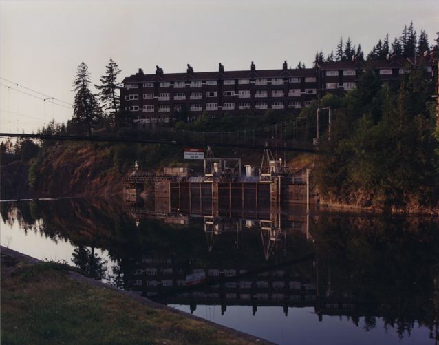
The underground facility is 270 feet below the top of the falls and about 600 feet in from the bottom rock face. Water is collected at a point about 300 feet from the edge of the falls. In this photo, I am standing near the elevator shaft and looking across the river. You can see the upscale Snoqualmie Falls Lodge in the background, and below that lies one of the two water intakes for the generators. The other intake is identical to my left out of the picture. You can also see a foot bridge crossing the river. Water enters and drops through an 8 foot diameter pipe in the same shaft with an elevator and the 2000 volt lines to the transformers where the voltage is boosted to 115 KV for distribution.
Click on any of the images below to see them enlarged.
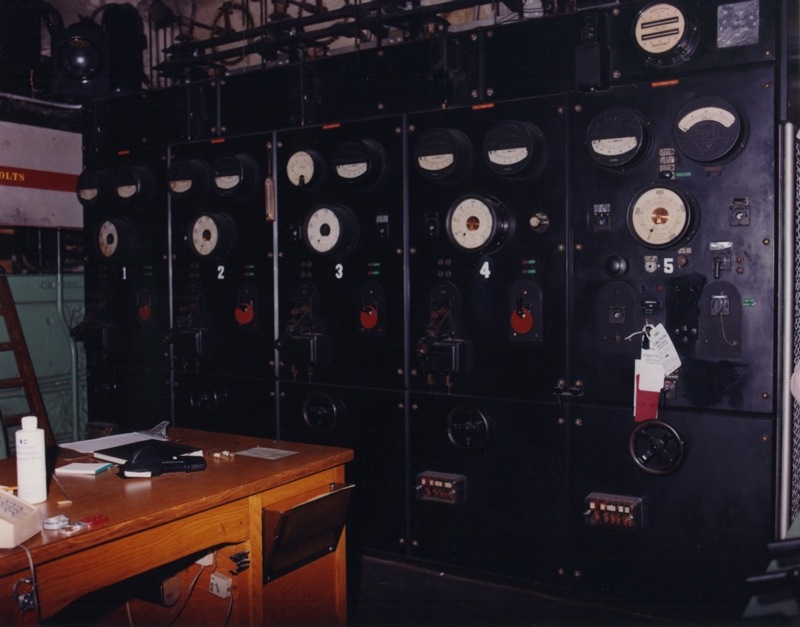
When you exit the elevator at the bottom you enter the control room, which is above the main generator floor. The cavity in the rock is approximately 50 X 100 feet and two stories high.
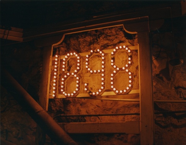
At the other end of the cavity is the dedication plaque with the year 1898 in light bulbs.
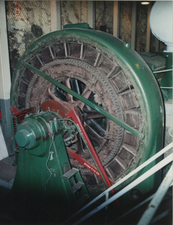
This photo is of Machine #3, one of the original 1.5MW generators made by Westinghouse.
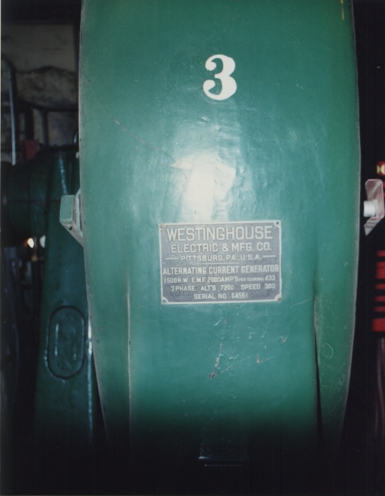
This is a close-up of the name plate and ratings on the #3 machine.
The Water Wheel System

The original wheels were of the "Pelton" design. The Pelton wheels were beginning to show wear due to water abrasion and were replaced around 1950 by the more efficient "Doble" design. The Doble wheel is a dual nozzle, quadrature excited, water wheel with 13 buckets. An actual bucket and nozzle can be seen to the left. The Doble wheel will produce 2500 horse power with a head of 268 feet at 300 RPM. This is a good match for the 1.5 MW machine. There are 4 such wheels, one for each of the 1.5 MW generators.
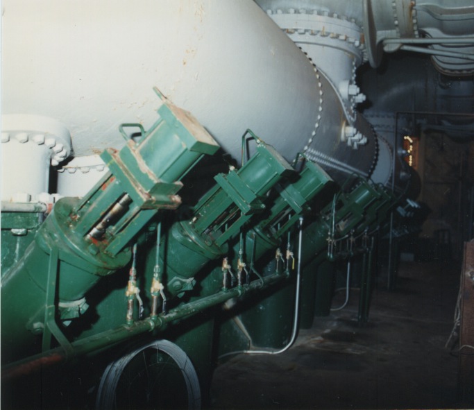
This photo shows one of the two water inlet manifolds for a pair of generators. The actuators for the needle valve assemblies are below the manifold. The manifold is the large gray pipe assembly in the upper left of the photo. One can also see the very edge of the 1898 dedication plaque in the background. There are lots of things that you don’t want to back into by accident here!
The US Department of Interior granted an extension of the operating license for forty years in 2004. The generating plant having been started in 1898 will operate to at least 2044. These are truly venerable machines that have and will continue to serve well.