5760 Preamplifier
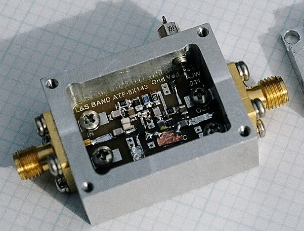
This preamp uses an Agilent ATF36077 FET, followed by an ATF54143 FET device. The design incorporates feedback to achieve simultaneous gain and noise match. The noise figure is approximately .9dB, and the input return loss is approximately 20dB. The preamplifier, which is the unit to the right in the photo, is shown attached to a 4 resonator preselector.
1296 Preamplifier
This amplifier uses the Agilent ATF54143 FET device mounted on an Agilent demo board. The amplifier uses inductive feedback to achieve simultaneous gain and noise match. A noise figure of .35dB and an input return loss of 20dB were achieved using this technique. This permits the use of a 3 resonator interdigital filter at the input of the amplifier. The filter we chose was designed by RE Fischer in March ‘68 QST. It is still featured in the 2010 ARRL HBK on 11.39. The bandwidth is approximately 110 MHz with loss of about .4dB. We measured .7dB noise figure for the combination. The filter is slightly smaller than the helical filter described in the 2 meter amplifier section below. We use a pair of these amplifiers in tandem at the base of the tower on our 1296 station.
432 Preamplifier
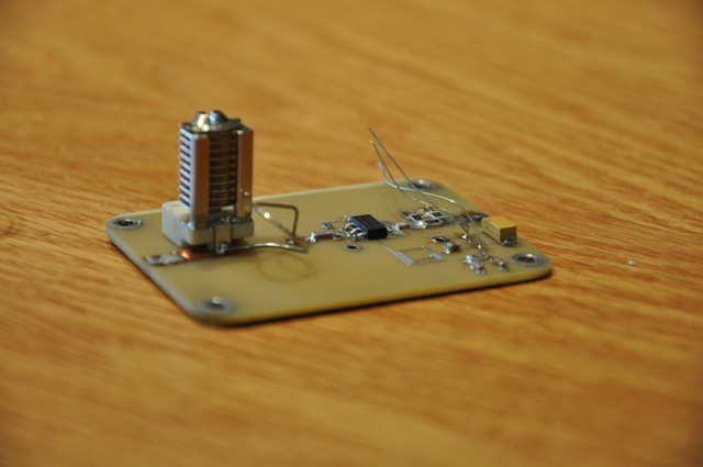
This photo shows one of the most current approaches to simultaneous gain and noise match using an integrated circuit device. The device used is a Hittite Microwave HMC616LP3E. This amplifier IC generally has good return loss with a sweet spot near 432 MHz. I measure about 19dB return loss in a 50 ohm system with 3 volts bias on the IC. The noise figure is slightly less than .5dB. All this performance without external design work! It is also economical.

I mentioned that I had designed single stage 432MHz amplifiers along with a three resonator interdigital filter some time ago. That filter measures out at about 45MHz bandwidth and .05dB insertion loss. The filter is not small, being approximately 8 x 10 x 2+ inches and weighing about 10 pounds. It is also silver plated.
Combining this filter with the Hittite IC preamp yields quite the acceptable shape with a noise figure just slightly over .5 dB.
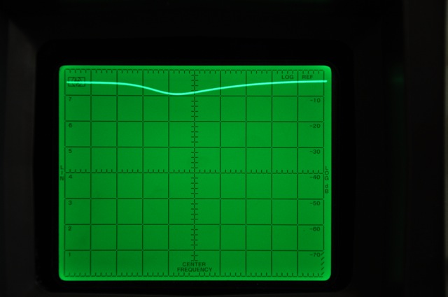
Note: Hittite has a line of amplifiers that work from a few hundred MHz to several GHz. Also, these devices are tiny, about 3 mm square. Be prepared to surface mount. The photo on the left shows the S11 parameter measurement.
2 Meter Preamplifier
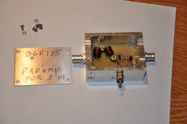
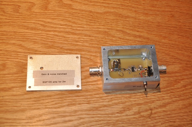
Both 6 and 2 meter YU1AW amplifiers using the BGF 135 transistor were laid out on the same prototype board. The photo at the left shows the completed amplifier.
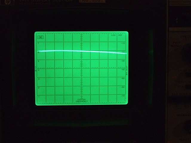
The second photo shows the best measured NF at 2.9 dB. The input return loss is next at 9 dB. The analyzer is set for 10 MHz/div span on all photos. Zero dB reference is at the top of the screen. Note that the return loss can be improved greatly by retuning the input network, but then the NF goes slightly over 4 dB. This again illustrates the bi-modal tuning condition favoring either match or noise figure. As with the 6 meter amplifier, the other parameters are acceptably close to those cited on the YU1AW web site.
Unfortunately for me, I have a rather strong interfering signal on the lower side and need additional selectivity beyond that available from this design.
Now for some interesting experiments. Fortunately for me, Dragan was kind enough to provide the S parameters for the BGF135. Upon analysis these looked very similar to some Philips BFR devices that I used some years ago at 432 MHz except that the parameters were proportioned to 144 MHz as opposed to 432 MHz. The S11 locus was about in the right place and Fbeta was positioned properly. Most of this is likely due to the larger geometry of the BGF135. Also the amount of additional emitter inductance was quite small, so small in fact that all that was required was to lift one of the two emitter leads to make the whole concept work.
I decided to use the same basic approach on the two meter design as I did for my old 70 cm design. I made the following modifications. I replaced the input network with an L network, added a 3 dB attenuator on the output to ensure some degree of broad band output termination and disconnected the right most emitter lead on the BGF135. You can see the modifications in the next two photos. The biasing and feedback were left as original.
Even better gain results might be obtained if the output attenuator is replaced with a diplexer. I have not tried this.
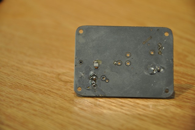
The underside of the modified board showing placement of the additional fixed capacitor (white square).
This is the best noise figure (about 1.4dB) on the modified amplifier.
Here is the input return loss of the modified amplifier at the best noise figure. 0dB reference is at the top of the screen, 10dB/div vertical and span is 10MHz/div. 145MHz is at screen center and return loss is about 25dB at center.
This photo depicts the complete amplifier in its case with all of the modifications.

The drawing at the left shows the schematic modifications that were made to the original design.
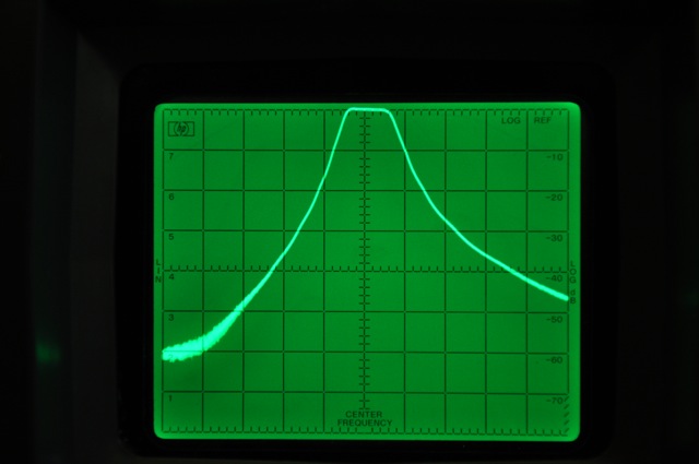
Here we have the response of a three resonator helical filter with 0.4 dB insertion loss that I designed. The span on the analyzer is 10MHz/div. Vertical is 10dB/div. The filter was tuned in a 50 ohm system. The filter dimensions are 1.25 inches by 2.75 inches by 4 inches. To regain selectivity, this filter will be added to the modified amplifier.
This photo shows the measured composite noise figure (1.9 dB) of the helical filter and the modified amplifier.
This photo demonstrates the composite gain and response of the filter amplifier pair. Note that the 0 dB reference is at -20 on the screen in this photo. The composite gain is 18 dB. The result is a very robust and practical amplifier with good selectivity and noise figure at the same time.
6 Meter Preamplifier

We upgraded our 6 meter station with the addition of stacked 7 element Yagi antennas and an Elecraft K3. We sought a high intercept, double tuned input preamplifier based on one of the new CATV transistors to complement the K3.
We decided to build a 6 meter preamp based on the YU1AW amplifier we saw in an article at http://yu1aw.ba-karlsruhe.de/bfg135aeng.htm. Susan (WB7BST) laid out the amplifiers using software and manufacturing facilities from Express PCB.
This is an interesting preamp with almost 500mw of standing power. It performs largely as suggested on the YU1AW website. Gain is also adequately close to the article.
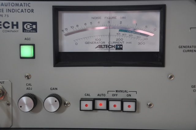
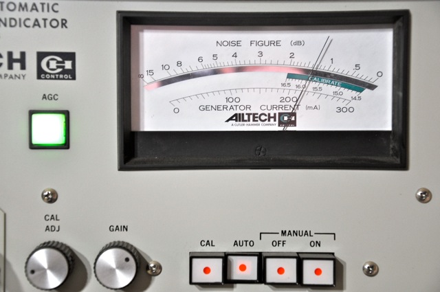
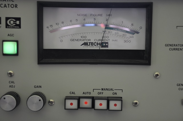
Input match and noise figure are interesting. Keep in mind that these are actual measurements, not simulations, done on an HP 8553 analyzer with tracking generator and an AIL 75 noise figure meter. The reflectometer has slightly over 25 dB directivity. All return loss photos are 10dB/div vertical and the 0 dB reference is at the top of the screen.


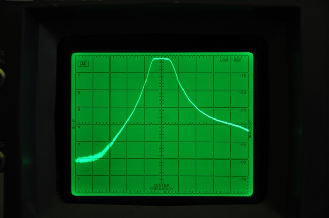
This preamp demonstrates the typical bi-modal input properties where Zmatch differs from Znf-opt. In the photo on the left, the amp is tuned for best input match. The span is .1MHz/ div with the center at 50.125 MHz. Notice that this is super tuned, the displayed return loss of 50dB is far better than the bridge with a good 50 ohm load. The next photo shows the noise figure of about 3dB with the input match.

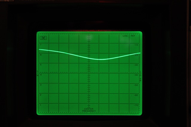
We tuned the amp for best noise figure which is about 2 dB. The photo shows a much flatter input return loss of about 9 dB. In the next photo, the span was increased to 1 MHz per division to show the gentle shape of the return loss.

It appears that there is some slight inductive feedback effect internal to the 135 due to the emitter ballasting resistors and bond wires, but not much. The delta NF between best NF and best match is about 1 dB NF. Considering the approximately 5,000 Kelvin sky on six meters, I think either setting would work well. The decision could be made on the basis of the existence of interfering services.